
Model the link and interfaces
Count patch cords, connectors, splices and passive devices. Identify connector type, fiber grade and polish.
A repeatable workflow reduces incompatible connectors, hidden loss and incomplete commissioning records.
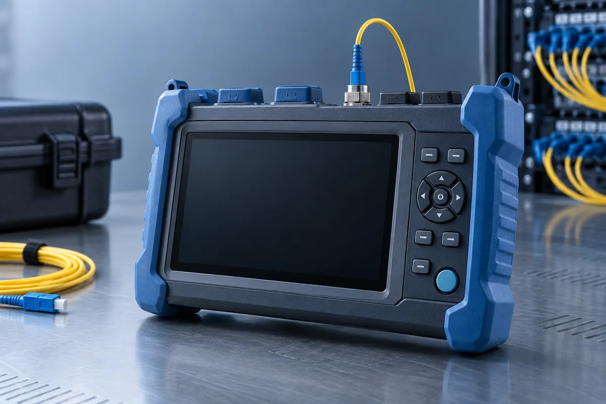
Record the endpoints, topology, route distance, required data rate, availability target, connector type, fiber grade and expected service life before choosing a patch cord or transceiver.
The checklist can be applied to FTTH, enterprise, data-centre, industrial and telecom links.
Count patch cords, connectors, splices and passive devices. Identify connector type, fiber grade and polish.
Add specified component losses and aging margin, then compare with the transmitter/receiver operating window.
Protect minimum bend radius and tensile limits; inspect and clean connector end faces before mating.
Use power/loss testing for channel acceptance and OTDR where event location or route evidence is required.
No single reading describes every aspect of a fiber optic patch cord link.
Checks contamination and end-face damage before a connector is mated.
Measures end-to-end insertion loss at the selected wavelength.
Estimates event location, reflectance and distributed attenuation along a route.
Confirms mapping before equipment is connected, especially for multifiber assemblies.
Commissioning records should connect each measurement to the patch cord identifier, endpoints, wavelength, reference method, equipment and date.
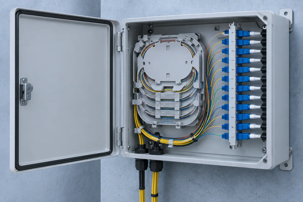
A concise technical brief makes patch cord and testing discussions more useful.